|
|||||||||||||||||||||||||||||||||||||||||||||||||


| Nederlands | French |
Using Tracealyzer for Linux To Evaluate Userspace PerformanceMohammed Billoo, founder of MAB Labs (www.mab-labs.com), provides custom embedded Linux solutions for a multitude of hardware platforms. In a series of posts he walks us through the Linux support in Tracealyzer v4.4, using a real-world project as an example.
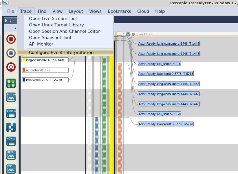
The vast majority of embedded Linux software developers write userspace applications. Since these applications are specific to a certain domain and are most certainly complex, application developers need an easy mechanism to validate the functionality of their applications and measure performance. In this blog post, we demonstrate how to create LTTng tracepoints and how to use Tracealyzer for Linux to measure certain metrics based on these tracepoints. We will focus on C/C++ this time, and demonstrate similar principles in Python in a future blog post. Tracepoints are instrumentation points provided by LTTng-UST (i.e., the LTTng userspace tracing library), which basically capture user-specified data as events. Tracepoints can be created in two ways: the first, called tracef, is a very simple way to capture all data as a single event. The second allows a developer to create custom events. While the latter mechanism requires significantly more code, it also provides maximum flexibility for collecting data and displaying it in Tracealyzer. We will use the tracef technique in this post, leaving custom events to a later post. As mentioned, tracef is very straightforward; the following snippet shows how to add tracing to a simple “Hello World” example: The lines in bold are all that are needed to log an LTTng userspace event: include the appropriate header file and call Make sure LTTng is installedWe must first ensure that LTTng is installed on our target embedded platform, using steps similar to those highlighted in the first post of this series. Then we need to cross-compile the above snippet, and run the following commands on the target platform to capture trace data so that it may be displayed in Tracealyzer: The items in bold are the most relevant since they enable capture of userspace data and execute the application. Another interesting point is that based on the above commands, we’re also capturing kernel traces and one may wonder why we’re doing that. This is for two reasons. First, having the kernel trace included can often explain the timeline of userspace events. For example, if we get a long delay in between two events in our application, kernel events should allow us to see what caused it. Second, Tracealyzer, as of version 4.4.2, actually requires some data in the kernel trace to correctly display UST events, although it doesn’t need to be the full kernel trace. The Percepio team is aware of this and are working on a solution for an upcoming release. Once a capture has been generated, the next step is to open it in Tracealyzer for Linux. After opening the trace, the first thing we need to do is to instruct Tracealyzer how to parse and display the userspace events. To do that, select Trace in the top menu, and click on Configure Event Interpretations:
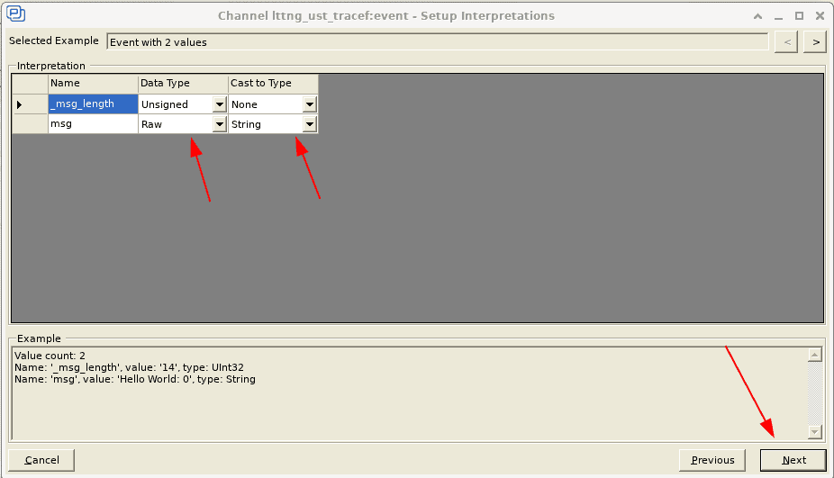
In the resulting window, highlight lttng_ust_tracef:event in the Channel Name column, and click the Change button. In the next window that appears, click the User Event Mapping radio button, and then Next to finally arrive at the configuration screen:
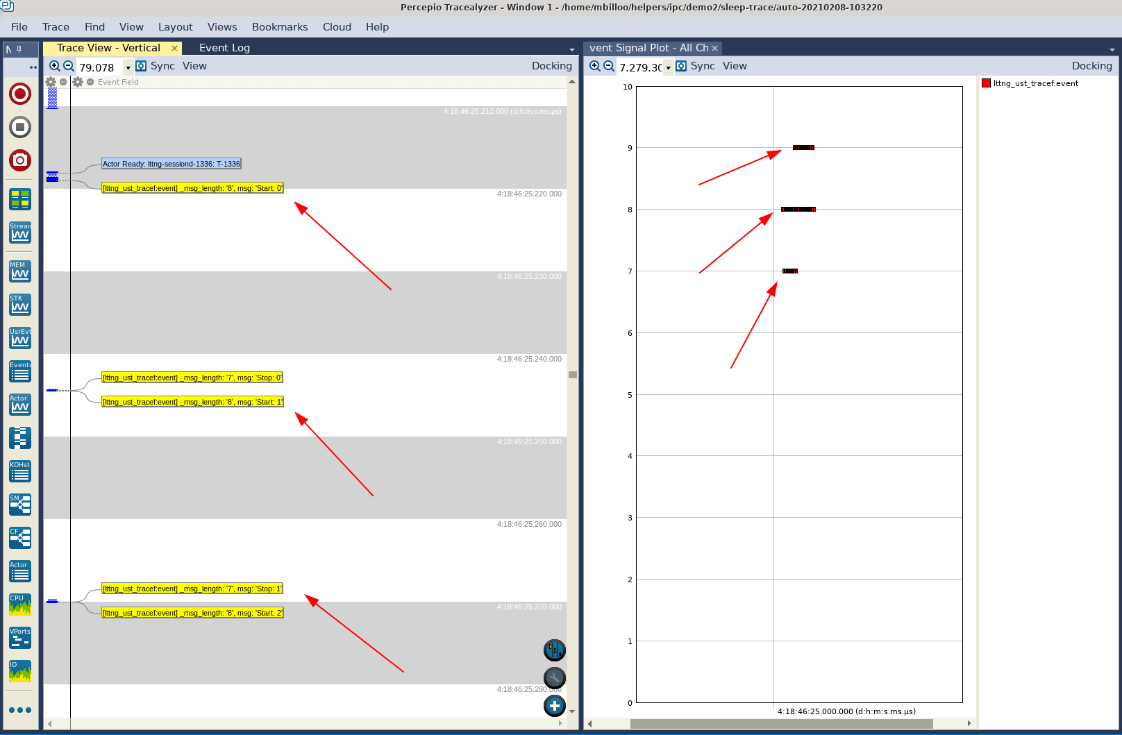
The second column, named Data Type, is the data type of each field as provided by LTTng. The third column, called Cast to Type, allows for changing (casting) the data type as needed. For instance, if some userspace trace point would log a numeric value as a string, the Cast to Type column allows for parsing the string as an integer. This way, we can use the integer value in Tracealyzer views, such as the User Event Signal Plot. Casting however requires a purely numerical string, so it cannot be used in this case. We leave the mapping as is and let Tracealyzer plot the message length to demonstrate the capability. There are better ways to log numerical values with LTTng-UST, as will be demonstrated in a later post. If we leave the columns as they are, and click Next, click Next again in the following window, and Finish in the final window, we return to the main Event Interpretation window where we can can click Apply and Reload Trace. Once Tracealyzer has reloaded the trace, it’s time to go to work. Open the User Event Signal Plot view by clicking the User Events button in the left icon list. Measure performanceIn the User Event Signal Plot, we notice that there appears to be only two data points, even though we have called tracef 25 times. Zooming in reveals that there are multiple dots, and zooming in even further we can see all 25 invocations of the tracef function. Note that the value (Y axis) increases after 10 invocations, as the string length then increases by one character! Also, clicking a dot (right below) causes Tracealyzer to highlight the corresponding invocation in the Trace View (left).
Now, let’s try to use Tracealyzer to measure the performance of a userspace application. In this specific example, we’re going to mimic a function that takes a certain amount of time with the Linux usleep function. We’re going to add a tracepoint before the function invocation and another one after to measure the time it takes for the function to complete: In a real world scenario, we would identify locations in our application where execution time needs to be measured and add the tracef invocations there. For example, a function may have multiple implementation candidates and we want to evaluate the execution timing to find the fastest algorithm. Or, a function may be complex and we want to characterize its execution. After compiling the above application, launching an LTTng session on the target, capturing and downloading the resulting trace data, we can open the trace data in Tracealyzer. If we set the filter to only show events from our application (“demo2-sleep”) and zoom in on the Trace View, we can see our familiar trace event:
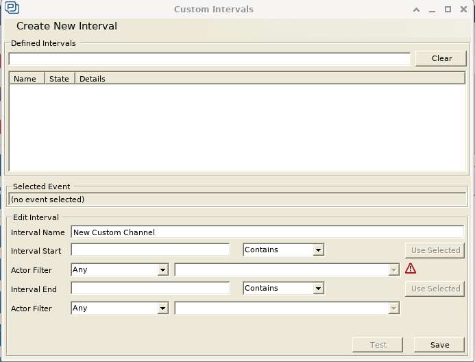
Now we’ll measure the execution time of the usleep function calls, which in this case can be defined as the time between each pair of Start and Stop events. The best way to do this in Tracealyzer is to create Intervals for our custom User Events. To do this, select Intervals and State Machines in the Views menu. In the window that opens, click Custom Intervals to arrive at the Custom Intervals configuration window where we can define a new data set consisting of intervals between selected events. This will allow us to extract timing information of key points in our application. Define your custom intervalA Tracealyzer Interval is defined by two events, its Start and Stop events, so we are going to create one interval that starts at the event that contains the string “Start” and ends at the event that contains the string “Stop”. To do this, we’re going to enter the following information in this window:
The Actor Filter fields allows us to specify a certain thread, but this is not necessary in this case. A final click on the Test button will tell us that Tracealyzer can find some intervals in the trace data that match the specified conditions. After saving the Custom Intervals definition, we can see that it appears in the Intervals and State Machines window and that Tracealyzer has highlighted it in the Trace View. Now, we can graph this interval timing, similar to how we’ve graphed the execution time of actors in the Actor Instance graph in a previous blog post. To do this, go to the Views menu and select Interval Plot – Select Set ….
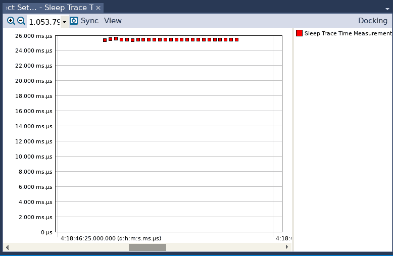
In the resulting window, highlight the name of our custom interval and click OK, and a new graph appears which shows the duration of our intervals. We can improve that graph quite a bit, to make it easier to read and interpret.
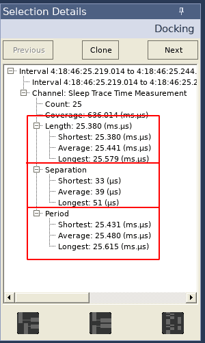
Not surprisingly, all interval executions seem to have lasted approximately 25 ms. And finally, clicking on one of these data points reveals valuable timing information about our interval in the Selection Details view:
The first box shows statistics on the length of each interval, which would correspond to the execution time of the function of interest (unless the thread is preempted by a context switch, but that would be visible in the trace view). The second box shows statistics on the time between executions of our function of interest (in our example, this would correspond to the time between a Stop event and the next Start event). The third box shows how often each interval occurs (the time from a Start to the next Start). The Interval Plot may be used to identify any anomalous timing of the function of interest, and the information in the Selection Details view can be used to gather high level timing statistics. ConclusionIn summary, the majority of embedded software developers will be developing userspace applications on their Linux-based embedded system. Tracealyzer, in conjunction with LTTng tracepoints, can be an invaluable tool to determine how well an application is performing, identify any anomalous behavior, and provide high level timing statistics. Tracealyzer can then be used to further troubleshoot any timing issues and improve performance of the application. This is the fourth in our series of articles about using Tracealyzer to capture and analyze visual trace diagnostics for embedded Linux systems. 05-04-2021 |
|


 Read more
 |
|||||||
 |
 |
 |
 |
 |
 |
||